Sichere Zahlungen
 Kostenloser Versand ab 85 € (DE, AT, FR)

Roller carriage conversion kit for the Bosch GTS 10j rip fence
Assembly instructions
Slight misalignment during parallel fence adjustment?
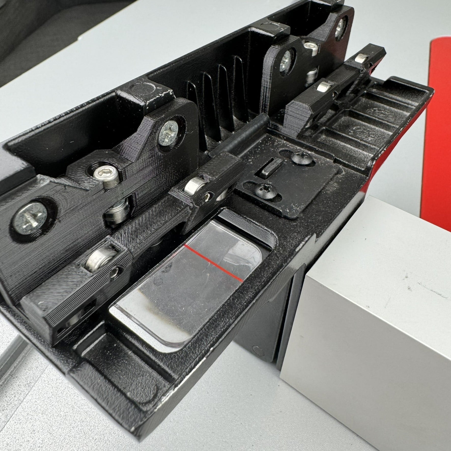
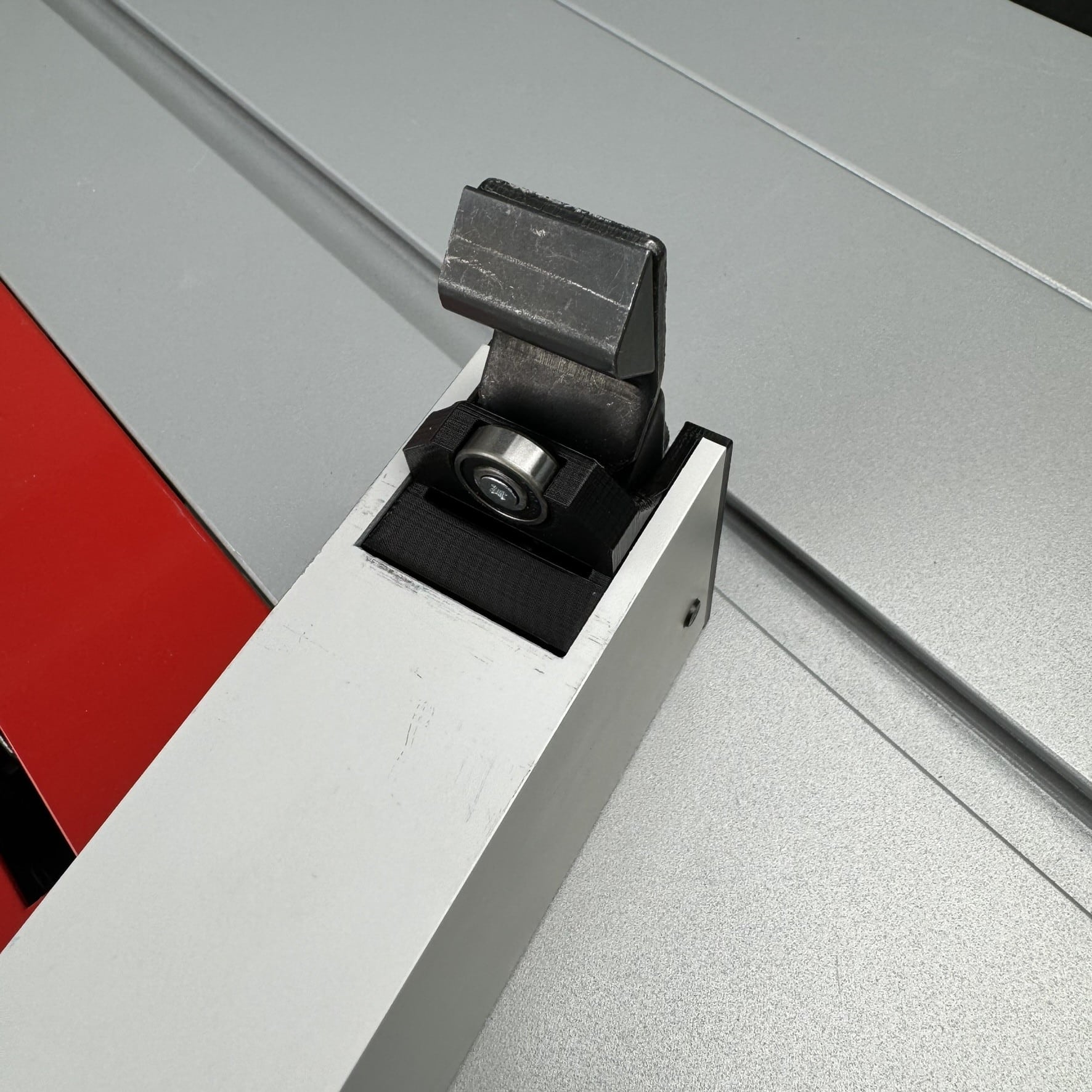
Our optimized sliding table for the Bosch GTS 10 J solves this problem! Thanks to 11 bearings and precisely adjustable rolling angles, the fence glides smoothly through the guide without any play. An additional ball bearing ensures constant parallel alignment with the saw blade – for perfect results.
straight cuts.
Light
- 2mm Allen key
- PH2 screwdriver
- Pin punch and hammer
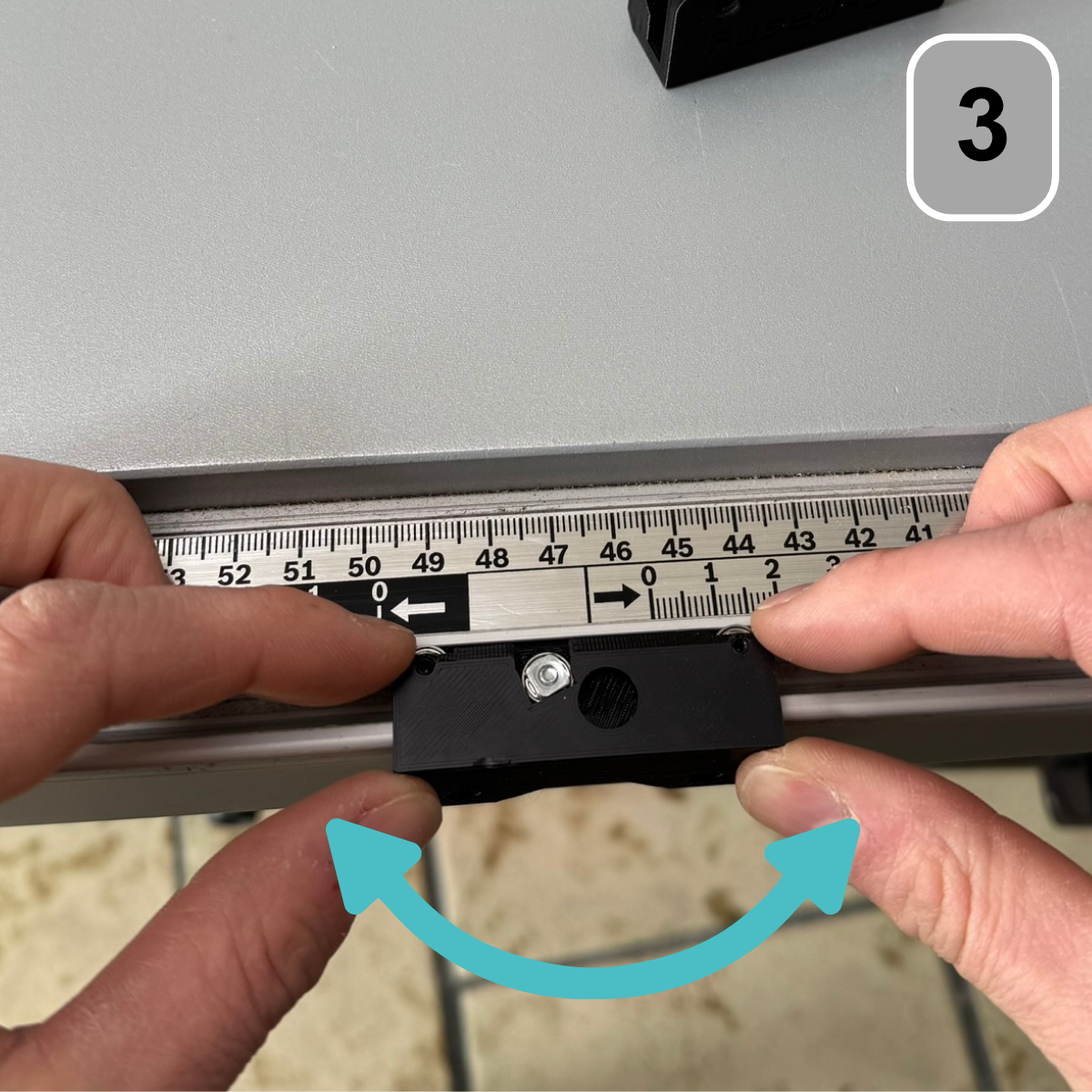
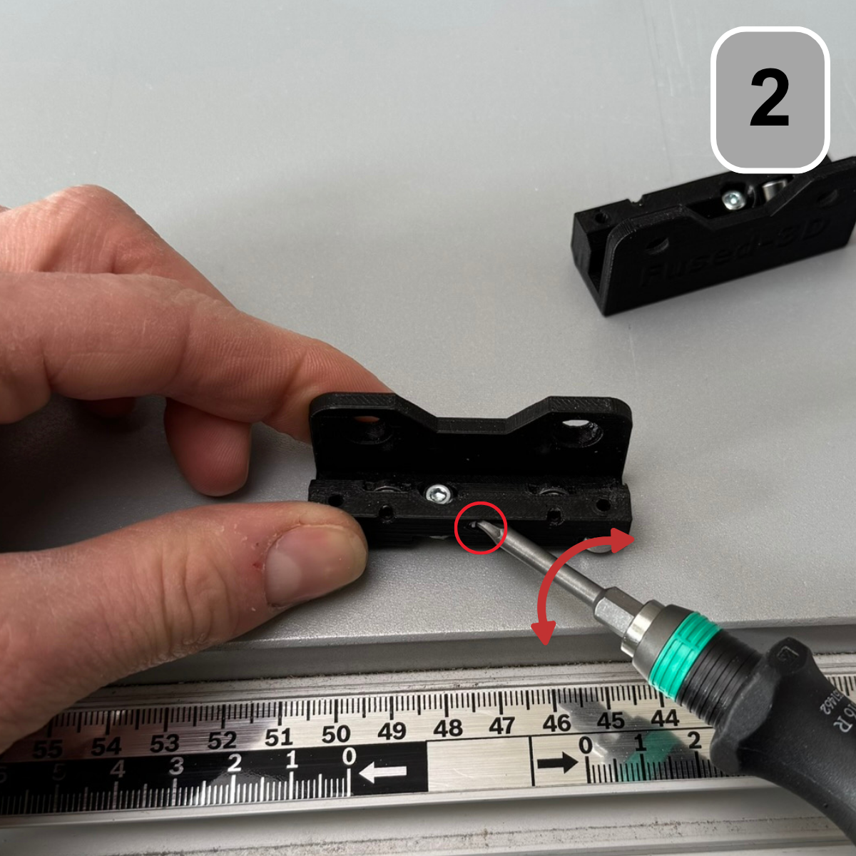
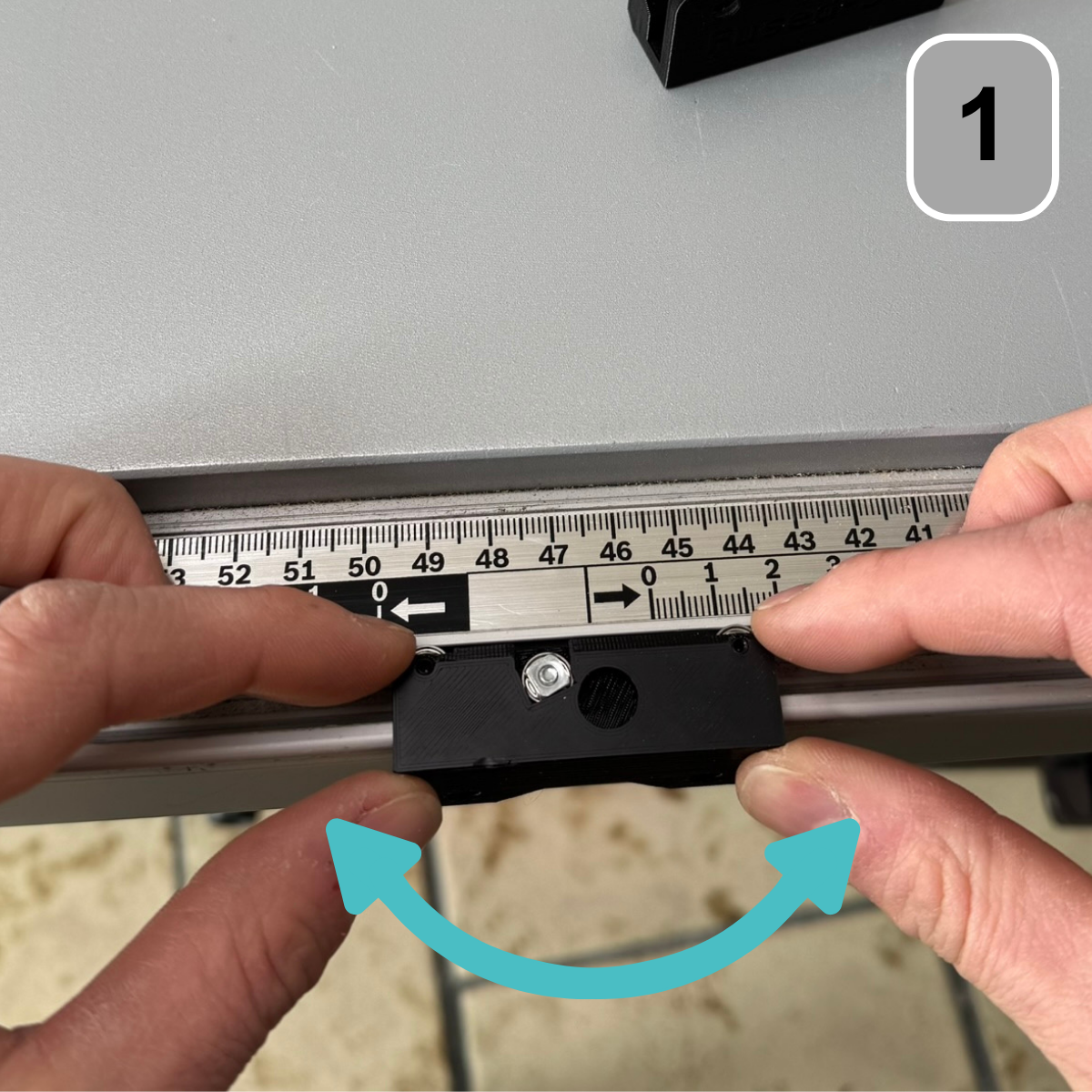
Step 1: Adjust the play of the ball bearings
All the following steps must be performed with both roller carriages!
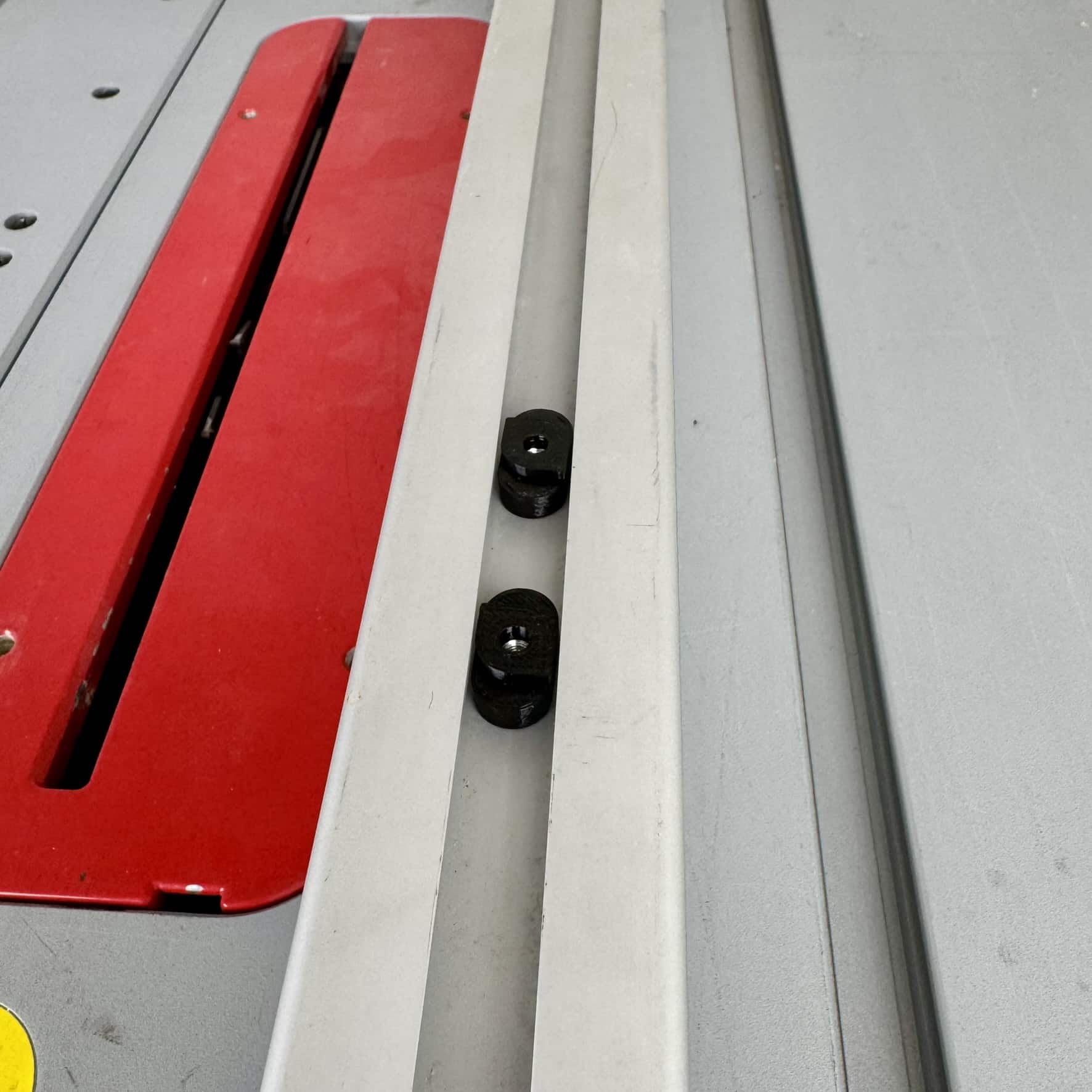
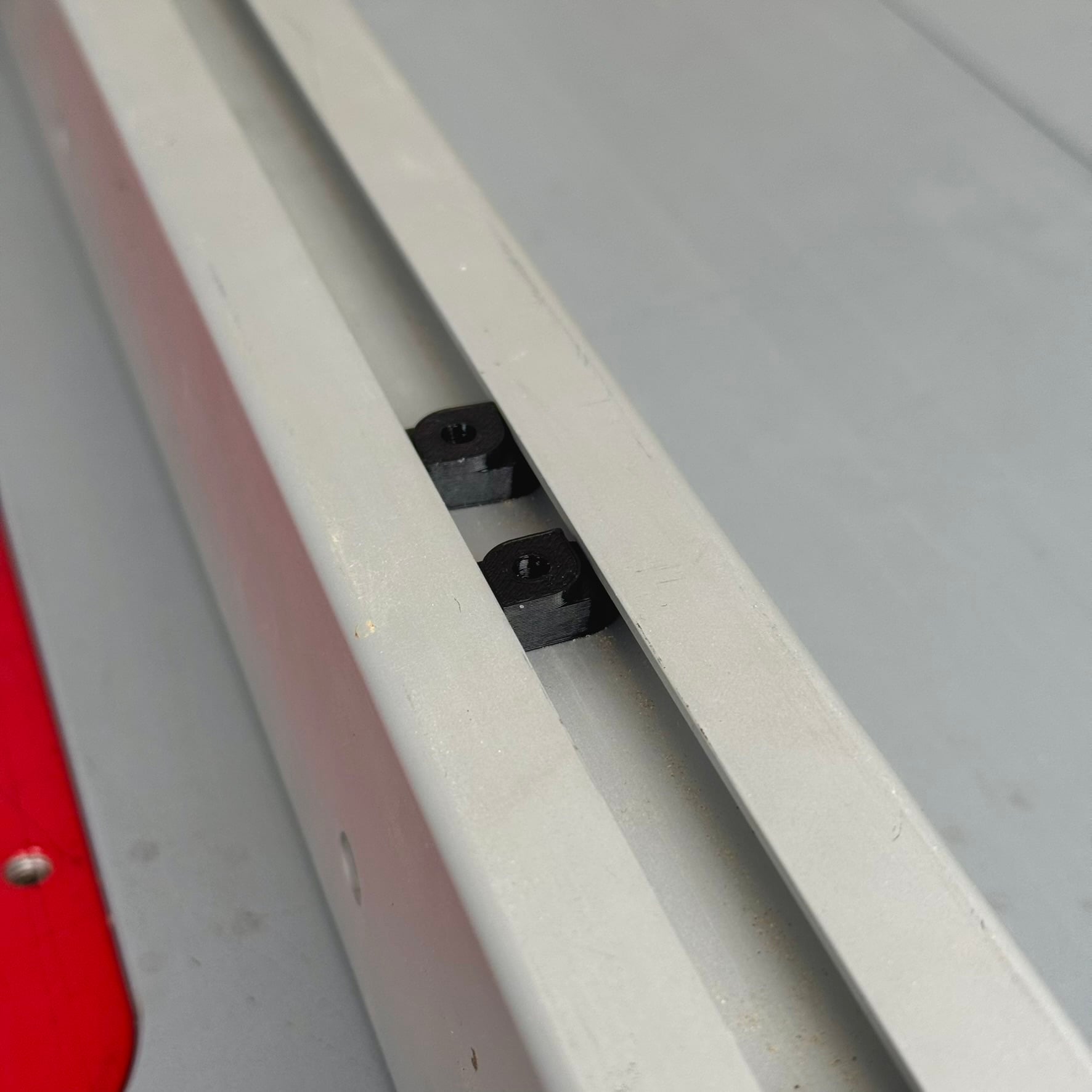
Insert the roller carriage into the aluminum profile of your saw. Carefully wiggle it back and forth to check how much play the roller carriage has.
Step 2: Adjust the play of the ball bearings
Remove the roller carriage from the aluminum profile again.
Threaded pin using a 2 mm hex key on the front
Turn the screw on the roller carriage clockwise to reduce play. Turning the screw outwards will loosen the play.
Step 3: Adjust the play of the ball bearings
After making a preliminary adjustment, reinsert the roller carriage into the aluminum profile. Check by wiggling it back and forth to see if the play has decreased. Once there is no more play, check if the roller carriage moves smoothly within the aluminum profile. Otherwise, repeat step 2.
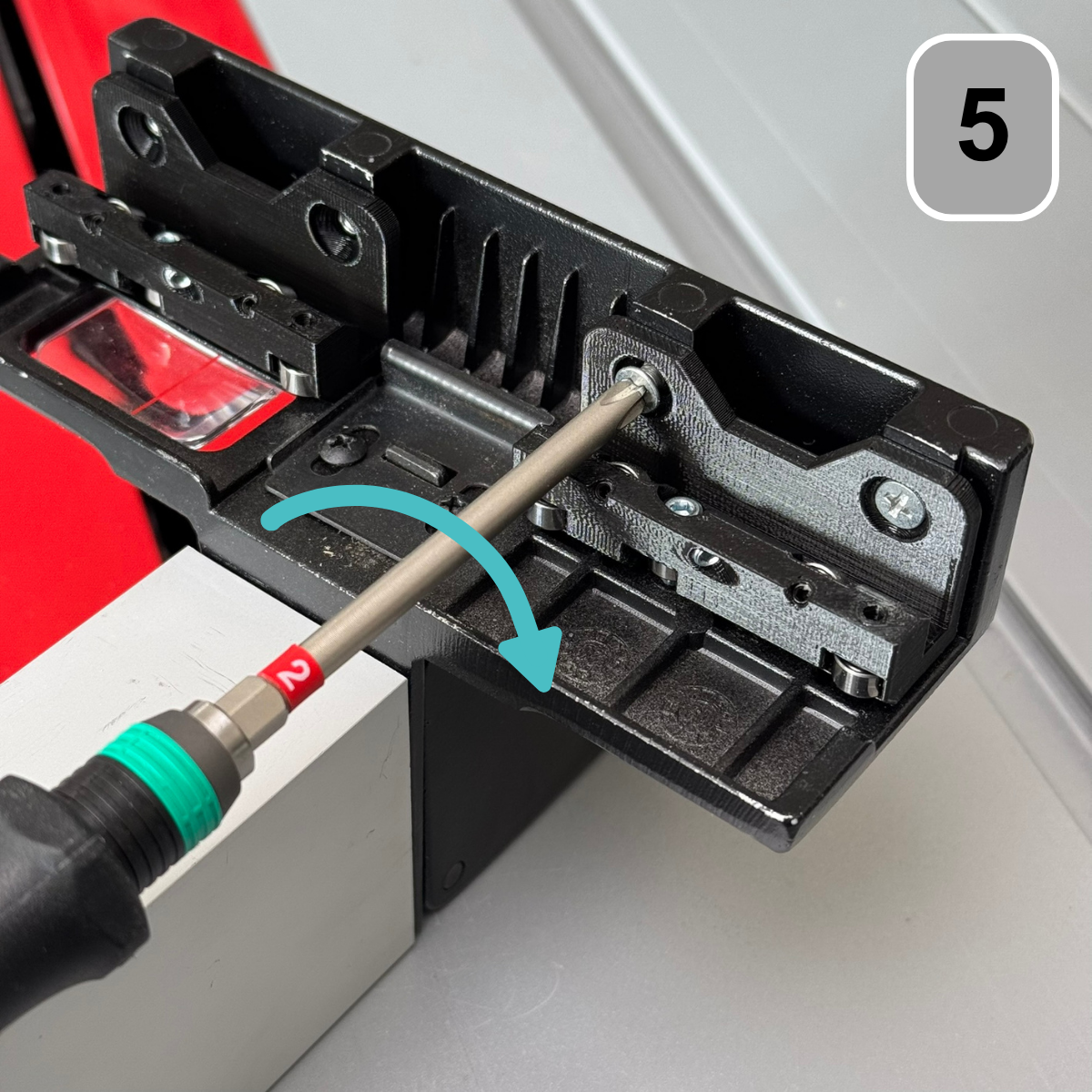
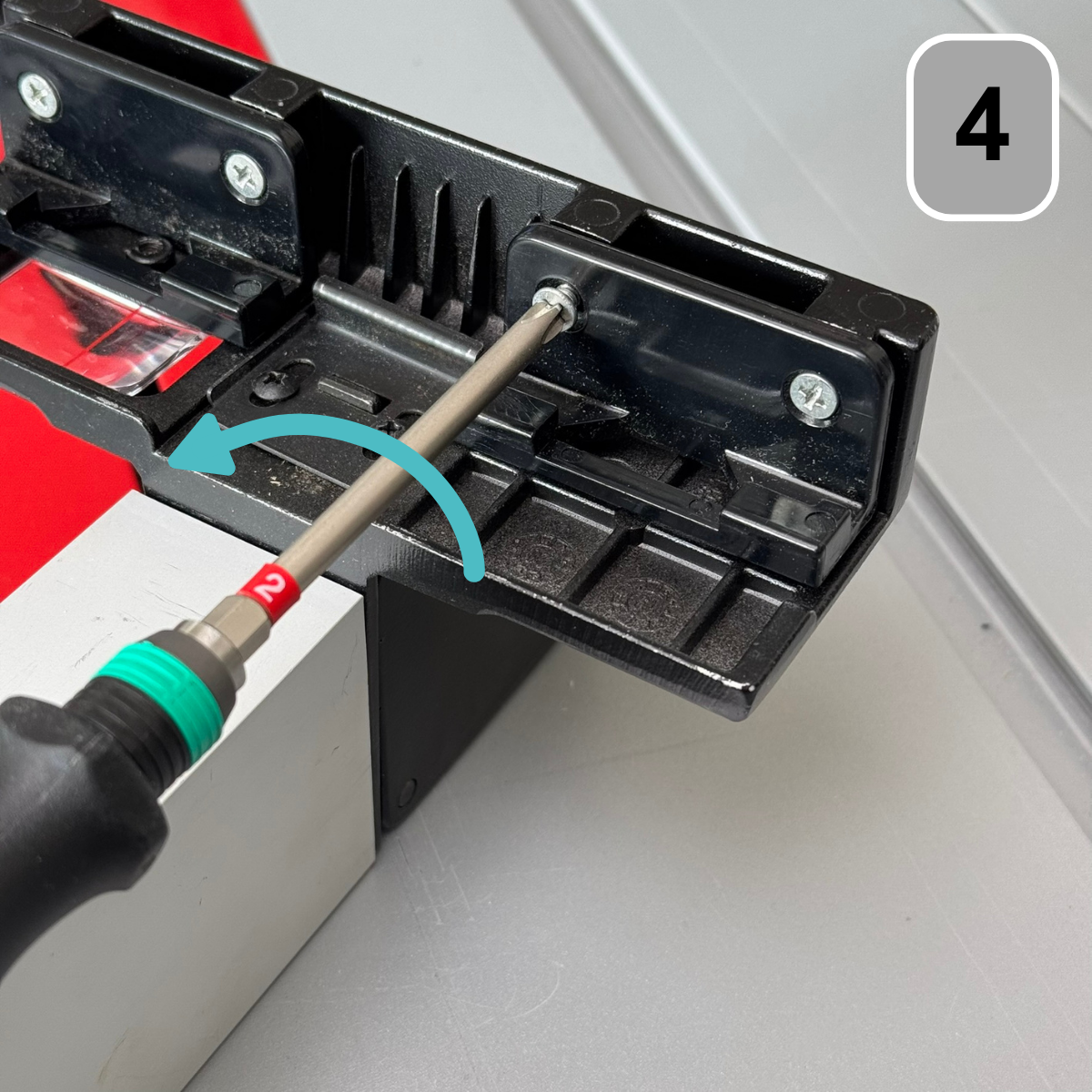
Step 4: Dismantling the sliding angle
Remove the original sliding carriages using a PH2 screwdriver.
Step 5: Mounting the roller carriage on the rip fence
Next, position both roller carriages against the parallel stop and
Attach them using the previously removed screws and a
PH2 screwdriver.
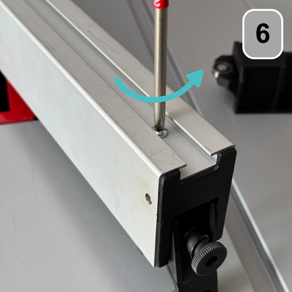
Step 6: Dismantling followers
When removing the follower, please be sure to wear safety glasses, as there are tensioned springs behind the tensioning mechanism.
Remove the thread-cutting screw from the back of the parallel fence. This is located on the top side and can be unscrewed with a PH2 screwdriver.
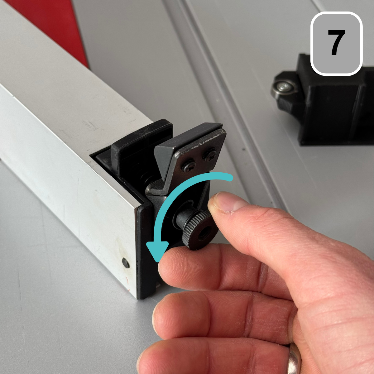
Step 7: Dismantling followers
Remove the knurled screw on the back, which is used for adjustment.
This serves to provide the tension. Ensure that a spring is located directly behind the knurled screw.
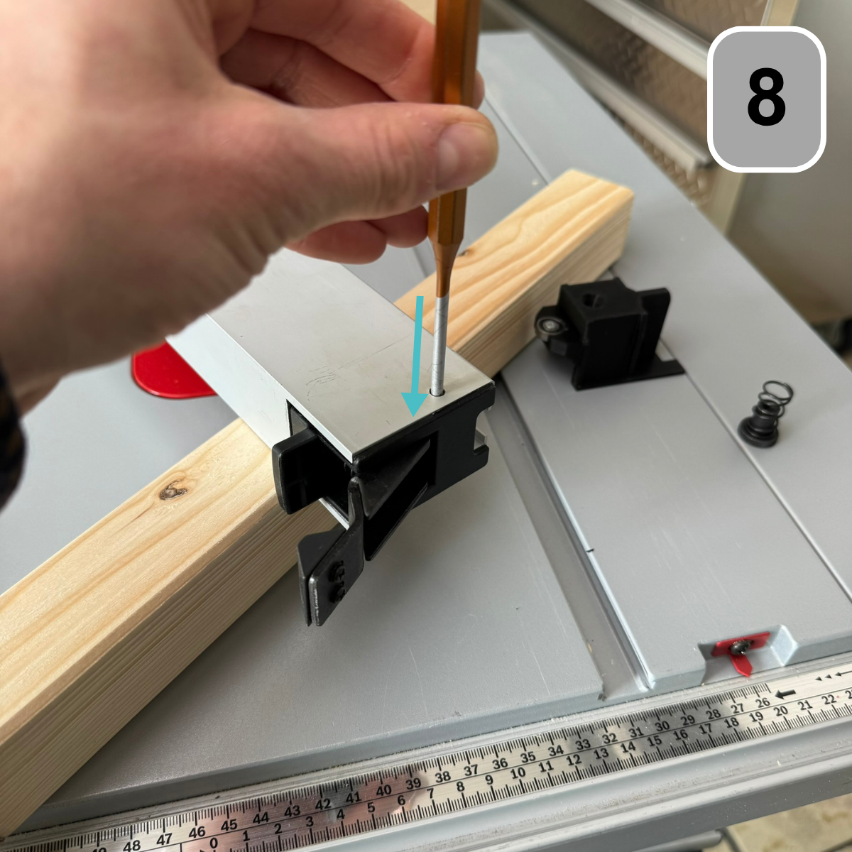
Step 8: Dismantling followers
Use a hammer and a pin punch or drift to carefully drive out the axle of the clamping lever.
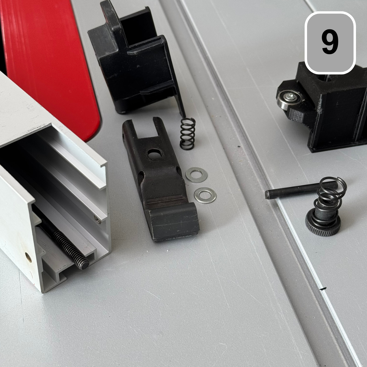
Step 9: Dismantling followers
The clamping lever and the follower can now be removed from the parallel stop. Pay attention to the spring and the two washers located behind the clamping lever.
Step 10: Assembly follower
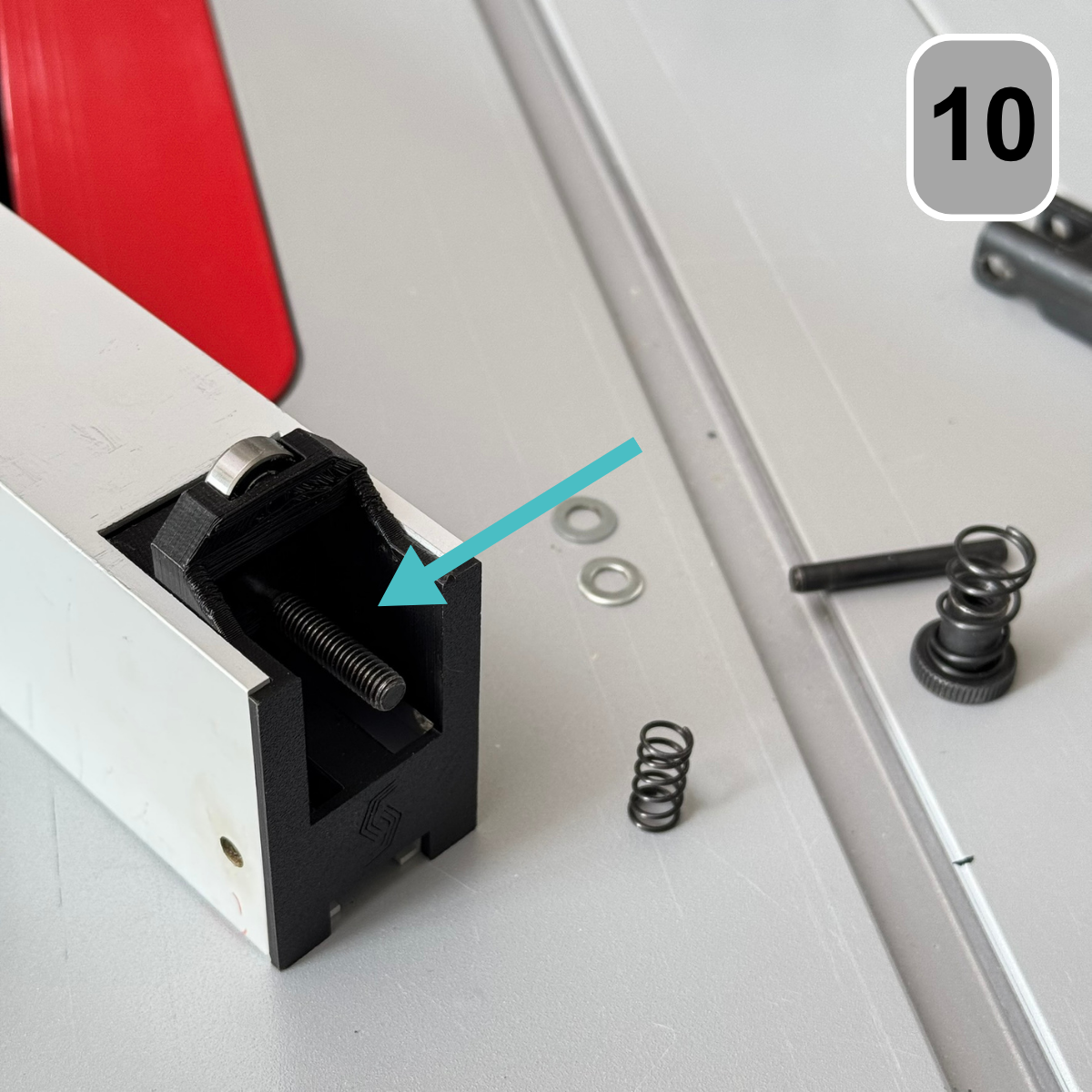
Please be sure to wear safety glasses when assembling the ball-bearing follower, as springs will be tensioned during the assembly process.
Insert the ball-bearing mounted follower into the parallel stop. The threaded rod must be threaded through the central hole in the follower.
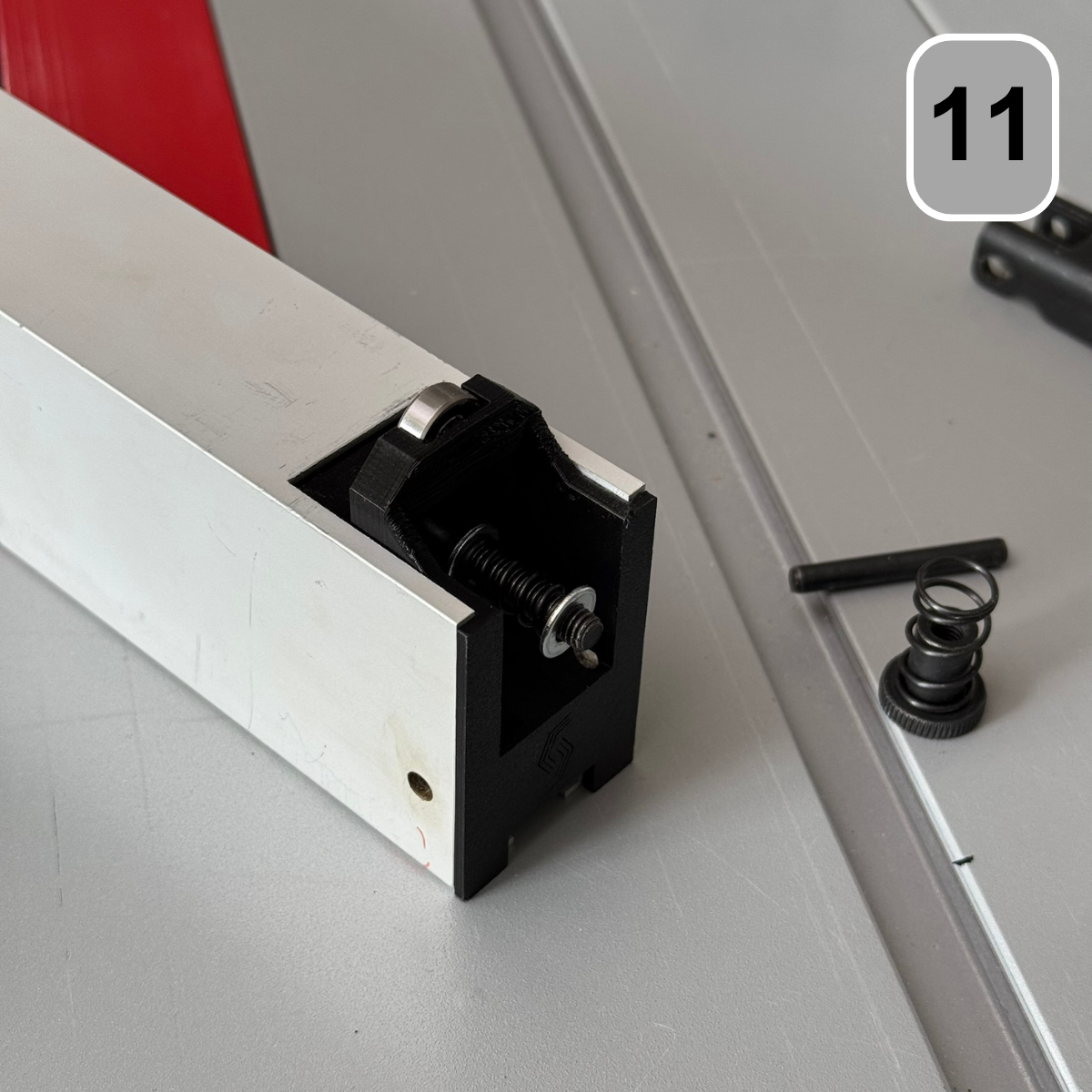
Step 11: Assembling followers
The following components are now mounted one after the other onto the threaded rod:
– 1 washer
– 1× compression spring
– 1 washer
Step 12: Assembly follower
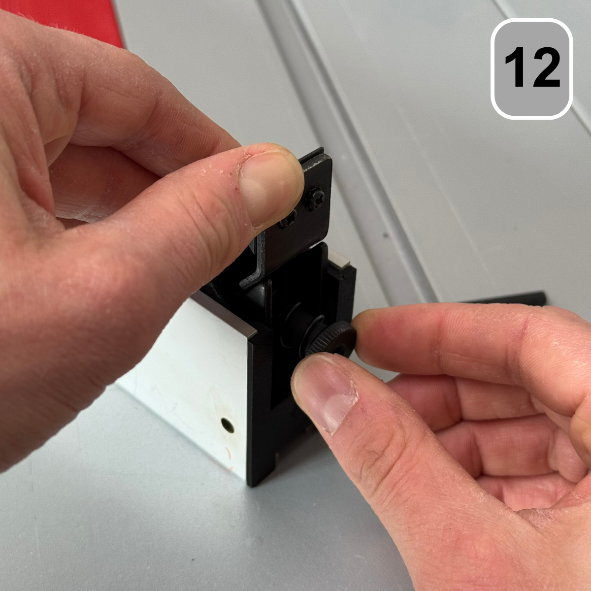
The clamping lever can then be mounted. To prevent this,
If this slips off the threaded rod, we recommend tightening the knurled screw.
to screw it on immediately afterwards.
Tip: If necessary, the threaded rod must be held in place at the front.
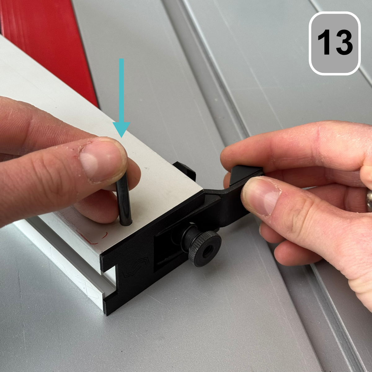
Step 13: Assembly follower
Push the axle of the clamping lever back into the parallel stop.
Make sure that the holes in the parallel stop and the clamping lever are aligned.
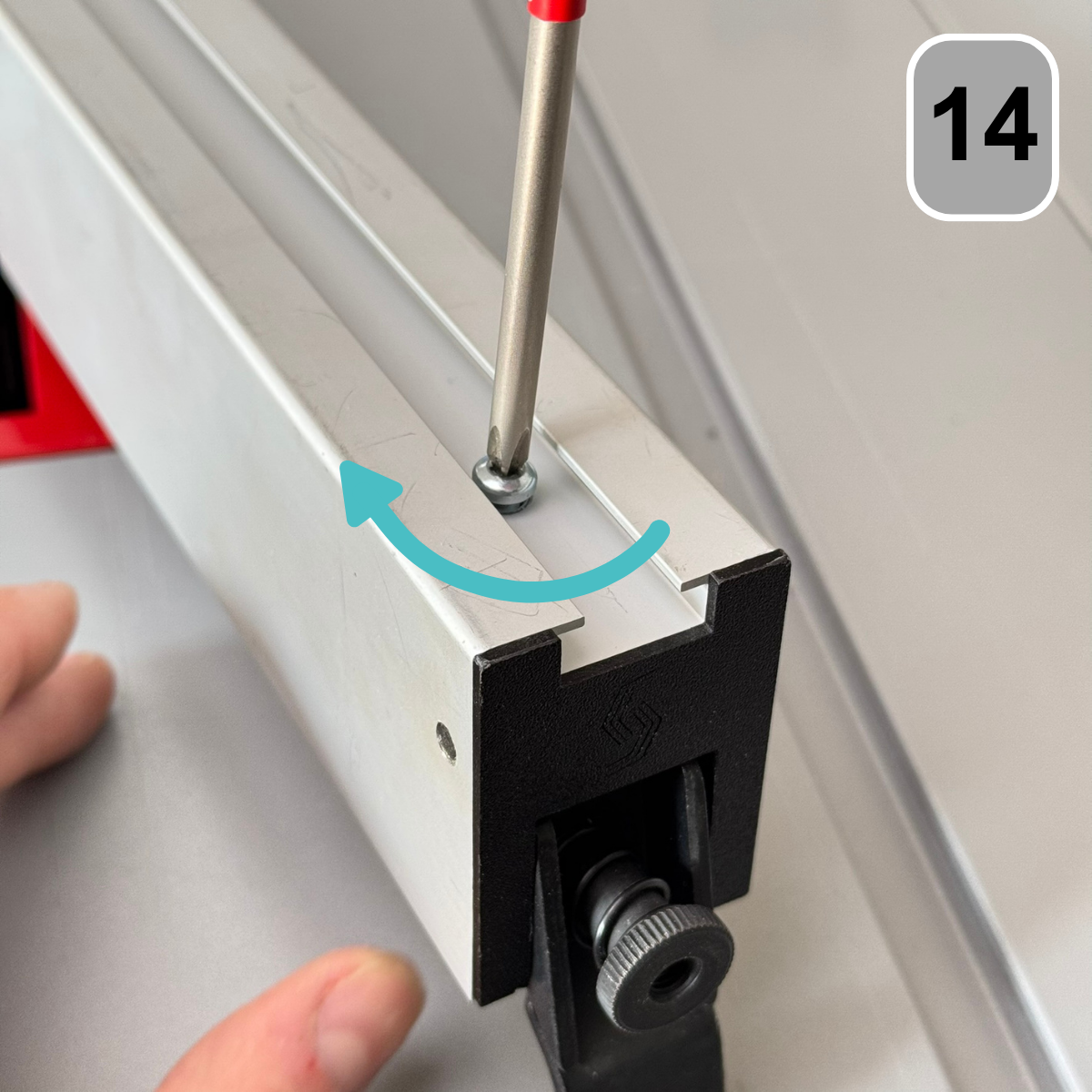
Step 14: Assembly follower
Then screw the thread-forming screw through the parallel stop into the roller carriage.
Step 15: Finishing
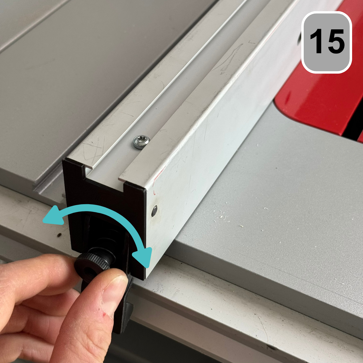
Finally, adjust the clamping force of the parallel stop accordingly using the knurled screw.
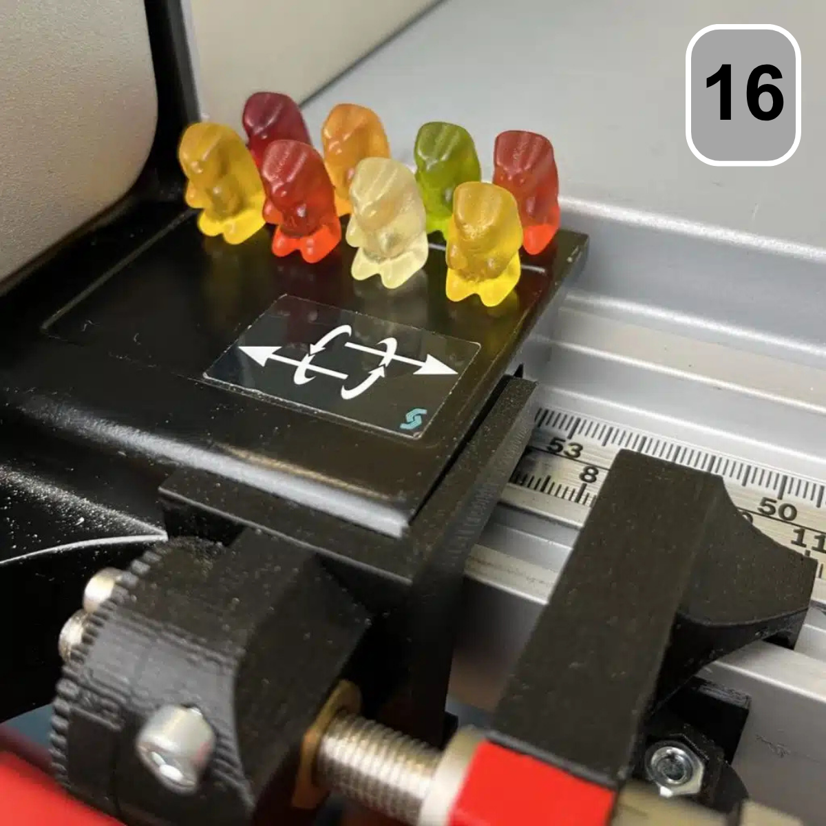
Step 16: Reward
Great job, you did it! Gummy bears are waiting for you as a reward. Enjoy!